Part III: Entropy and Engineering Applications · Topic 8 of 8 · 19 min read
Power, Refrigeration and Integrated Cycles
Combine state properties and balances to evaluate practical cycle models.
What you'll learn
Calculate performance for simplified vapour power cycles.
Identify components and heat flows in refrigeration and heat pumping.
Analyse ideal gas-turbine cycles using state temperatures.
Check cycle energy balances and realistic efficiency limits.
Understand the concepts
A cycle is a sequence of devices
Power and refrigeration cycles connect multiple steady-flow components. Each device changes pressure, enthalpy or temperature in a distinct way. Label states at component boundaries before calculating any cycle metric.
Vapour power cycle layout
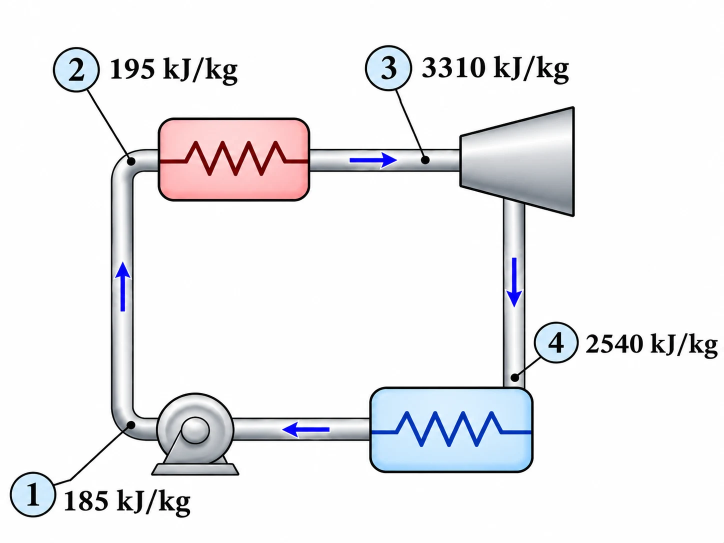
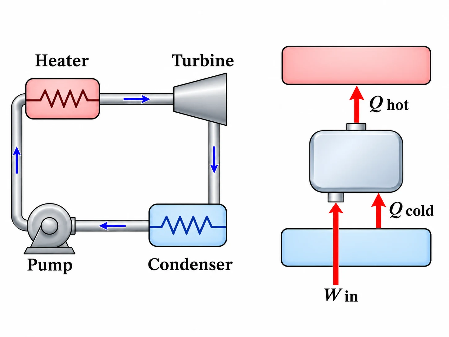
A simple vapour power cycle uses a liquid pump, heater, expander and condenser. Pump work raises the pressure of liquid, the heater adds energy, the expander produces shaft power and the condenser rejects heat. Enthalpy differences give specific heat and work interactions.
Net cycle output
Useful net shaft work is turbine work minus pump work. Heat input is the enthalpy rise through the heater. The resulting thermal efficiency compares the net work with that supplied heat rather than with the turbine work alone.
Refrigerator versus heat pump
A refrigerator is judged by heat removed from its cold region per unit work input. A heat pump is judged by heating delivered to its warm region per unit work. Their coefficients of performance can exceed one because work transfers additional environmental heat.
Ideal gas-turbine model
A simple ideal gas-turbine cycle has isentropic compression, constant-pressure heat addition, isentropic expansion and constant-pressure cooling. Compressor and turbine temperature changes give their specific works. The turbine must deliver more than the compressor consumes for positive net output.
Performance and idealisations
Simplified cycle analyses often assume negligible pressure losses, fixed heat capacities and reversible compression and expansion. Actual equipment departs from these assumptions. Always state whether you computed an ideal limit or a real operating estimate.
Assumptions and sign conventions
Use explicitly supplied property values for vapour-cycle states.
Treat the listed devices as steady-flow and neglect motion-energy changes unless specified.
Use ideal-gas isentropic relations only for the idealised gas-turbine model.
Equations that matter
Step-by-step method
Label device boundaries and number every state consistently.
Write a one-inlet one-outlet energy balance for each device.
Compute component-specific work and heat interactions from supplied state properties.
Combine devices to find net work, efficiency or coefficient of performance.
Check energy closure and whether performance respects second-law limits.
Worked example: Efficiency of a simplified vapour power loop
Four device boundaries have specific enthalpies , , and in the order pump inlet, heater inlet, expander inlet and condenser inlet. Find the idealised cycle efficiency.
Common mistakes
Forgetting pump or compressor work when calculating net cycle work.
Confusing refrigerator and heat-pump COPs.
Applying gas-only ideal relations to two-phase vapour without property data.
Using Celsius instead of kelvin for reversible performance limits.
Check yourself
Why is turbine work larger than net power-cycle output?
How can heating COP exceed one without violating energy conservation?
Which device in a vapour power cycle rejects heat?
Ready to try it yourself?
Independent Waypoint Mentor learning material. Not affiliated with or endorsed by any university.