Kirchhoff's laws
Physics · Senior school and first-year physics · about 10 min
Many circuits cannot be solved by combining resistors in one simple series or parallel chain. Kirchhoff's laws let you write reliable equations for currents at junctions and voltage changes around closed loops. The challenge is usually keeping track of signs rather than choosing a complicated formula.
The key idea
At every junction, current is conserved; around a closed circuit loop, potential changes sum to zero:
Currents are measured in and voltage changes in .
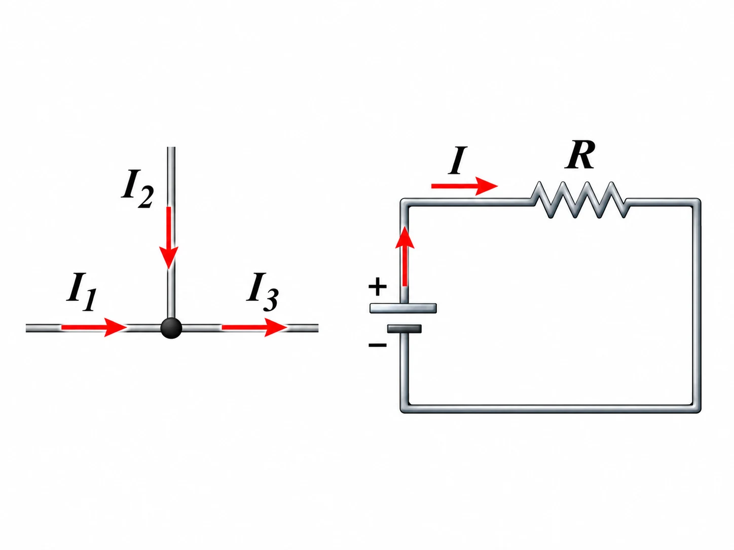
Junction rule for current
At a junction, charge cannot build up indefinitely in a steady circuit. Therefore, the total current flowing into the junction equals the total current leaving it. Start by drawing a direction for each unknown current; the direction can be chosen arbitrarily. If an answer is negative, the actual current flows the other way. Current is the same through series components, but it can split between parallel branches. In equations, either write the incoming currents equal to the outgoing currents or give each current an algebraic sign and set their sum to zero. Do not mix the two conventions.
Loop rule for voltage
Travel once around any closed loop. Across a resistor in the direction of conventional current, the potential change is ; moving against the current gives . Across an ideal battery from its negative to its positive terminal, the change is , and the reverse traversal gives . Add these changes and set the total to zero. Label battery polarity and choose a loop direction before writing terms. An ideal wire has no voltage drop; a real circuit may need extra resistance terms if the problem includes them.
Shared resistors and mesh currents
For a planar circuit with two adjacent loops, choose one mesh current for each loop, perhaps both clockwise. In an outer resistor, the branch current is just its mesh current. In a resistor shared by both loops, the mesh contributions run in opposite directions. If the first mesh crosses it downwards, use for downward branch current and a drop when traversing downwards. Apply the loop rule to each mesh and solve the simultaneous equations. Finally, use the junction rule to check the directions of the branch currents.
Worked example: Two loops with one shared resistor
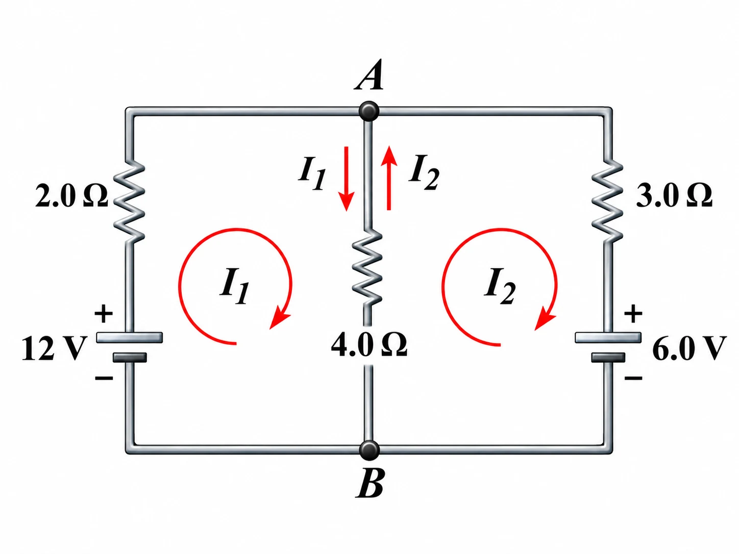
A circuit has two rectangular meshes side by side. The left outside branch contains an ideal battery with its positive terminal at the top and a resistor in series. The right outside branch contains an ideal battery, also positive at the top, and a resistor in series. A resistor forms the common centre branch between the same top and bottom junctions. Define both mesh currents and clockwise. Find both mesh currents and the current through the centre resistor.
Show the solution
Step 1: Write the left loop equation. The left mesh goes upwards through its battery and downwards through the centre resistor:
Step 2: Write the right loop equation. The right mesh goes downwards through its battery and upwards through the centre resistor:
Step 3: Solve the simultaneous equations.
6I_1-4I_2&=12,\\ -4I_1+7I_2&=-6,\\ I_1&=\frac{30}{13}=2.30769\ldots\,\mathrm{A},\\ I_2&=\frac{6}{13}=0.461538\ldots\,\mathrm{A}. \end{aligned}$$ **Step 4: Find the centre-branch current.** The left mesh drives current down the shared resistor, while the right mesh drives it up:I_{\mathrm{centre}}=I_1-I_2=\frac{24}{13}=1.84615\ldots,\mathrm{A}.
**Answer: $I_1=2.31\,\mathrm{A}$ clockwise, $I_2=0.462\,\mathrm{A}$ clockwise and $1.85\,\mathrm{A}$ downward through the centre resistor.**Common mistakes
Reversing a battery sign without checking the terminals
Write when travelling from negative to positive and in the reverse direction.
Using for opposing mesh currents in a shared resistor
Draw the mesh arrows; in the common branch their contributions oppose, so use a signed difference.
Adding resistor drops without a consistent traversal direction
Choose the loop direction once and assign each drop or rise from that direction.
Rejecting a negative calculated current
Keep the result and reverse the assumed arrow to interpret the actual direction.
Check your understanding
1. At a junction, currents of and enter. One outgoing current is . What is the other outgoing current?
2. A single loop contains an ideal source and resistors of and in series. What is the current?
3. Two clockwise mesh currents oppose each other through a shared resistor. In the downward direction, and acts upwards. What is the downward voltage drop across that resistor?
Still not sure? Talk it through.
Waypoint Mentor's tutor explains this out loud, works through your own problems on a whiteboard, and checks you've got it. Free to start.