Shear force and bending moment diagrams
Engineering · First- and second-year engineering · about 12 min
A shear force diagram (SFD) and a bending moment diagram (BMD) show what's happening inside a beam at every point along it. Engineers use them to find where a beam is working hardest, because that's where it will crack, bend too much, or need to be thicker.
The key idea
Shear force and bending moment are linked: the slope of the bending moment is the shear force.
So the bending moment is greatest where the shear force crosses zero, and the change in moment between two points equals the area under the shear force diagram between them.
Try it yourself
What shear force and bending moment mean
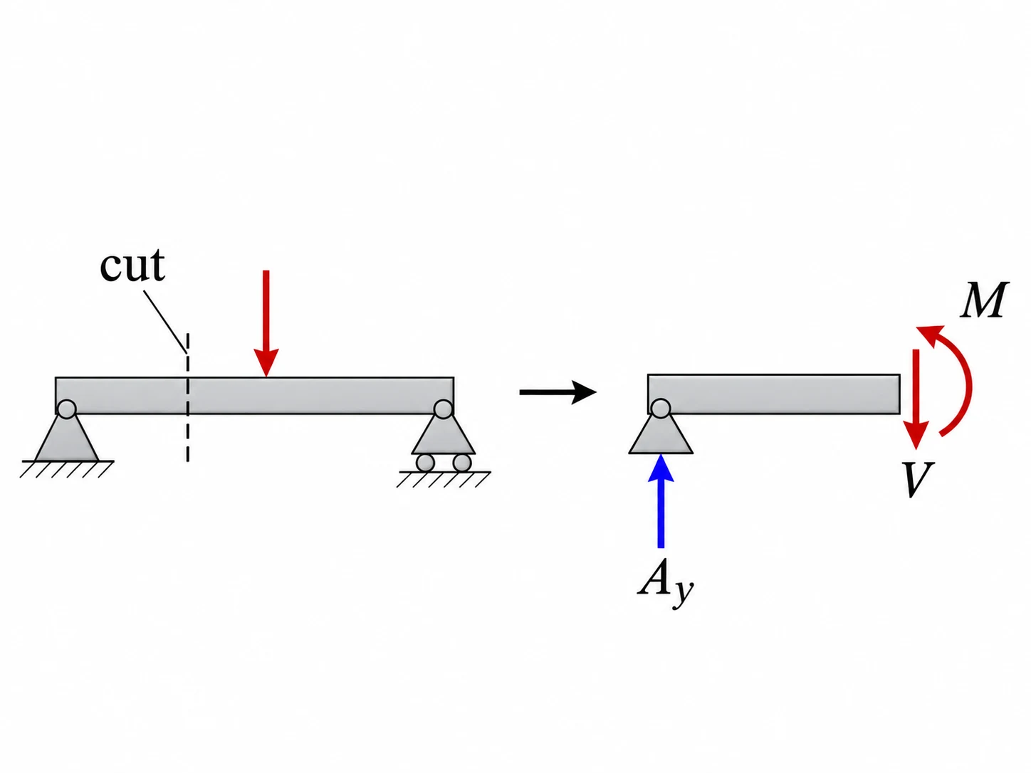
Imagine cutting the beam at a point.
- The shear force is the net vertical force on one side of the cut: it's what tries to slide one part of the beam past the other.
- The bending moment is the net moment on one side of the cut: it's what tries to bend the beam there.
You can use either side of the cut; both give the same answer if you keep the sign convention consistent.
Rules that make the diagrams fast
- Point load: the SFD jumps by the size of the load; the BMD has a sharp corner there.
- No load between two points: the SFD is flat; the BMD is a straight sloping line.
- Uniformly distributed load: the SFD slopes in a straight line; the BMD is a curve (a parabola).
- Simply supported ends: the bending moment is zero at a pin or roller.
- Maximum moment: where the SFD crosses zero.
Results worth remembering
For a simply supported span :
| Load | Maximum bending moment |
|---|---|
| Point load at mid-span | |
| UDL over the whole span |
They're handy for checking your diagram, but always work the actual case through.
Worked example: a point load off-centre
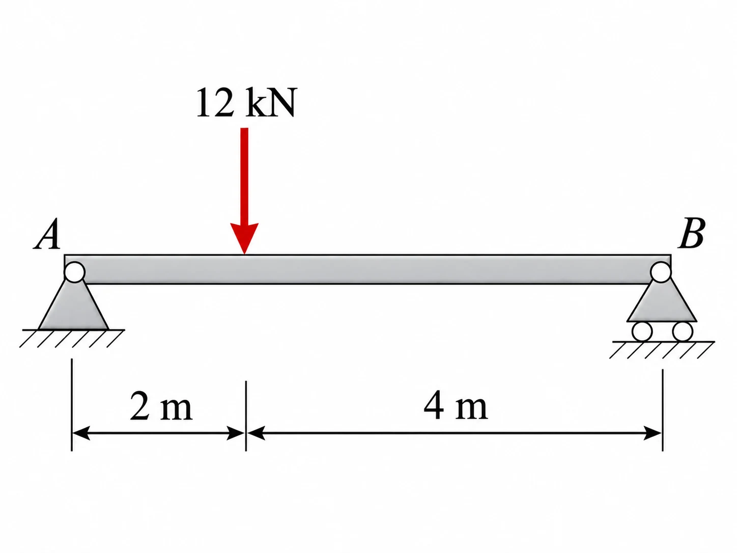
A simply supported beam is m long, with a kN point load at m from the left support . Draw the shear force and bending moment diagrams and find the maximum bending moment.
Show the solution
Reactions. Moments about : , so kN. Then kN.
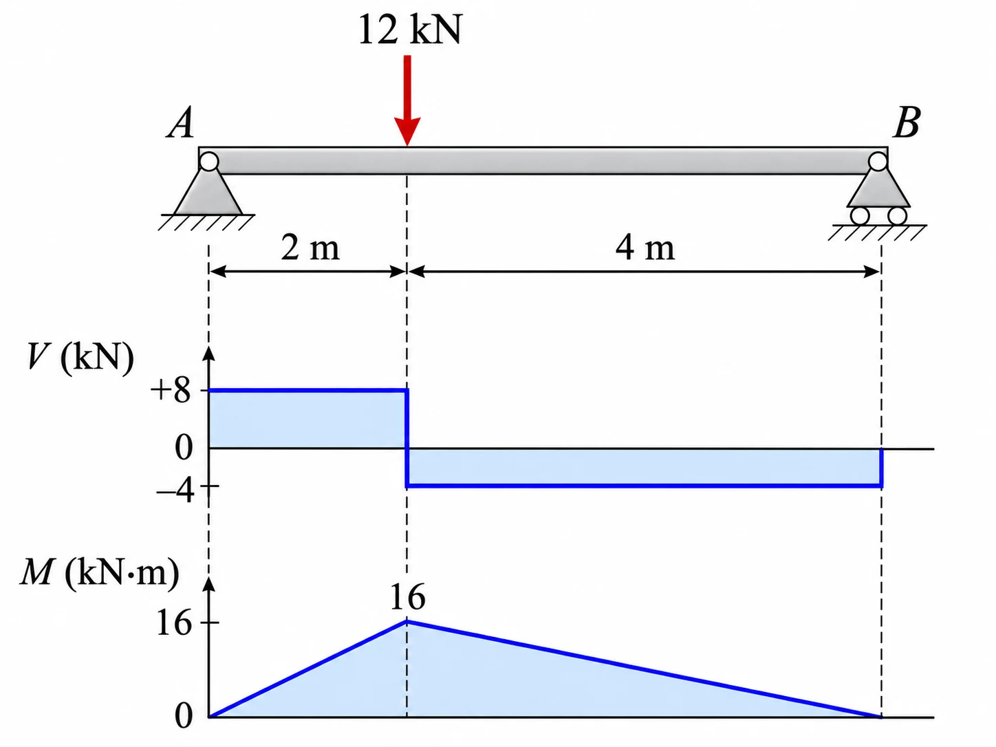
Shear force.
- From to the load ( to m): kN (flat).
- At the load the SFD drops by kN.
- From the load to ( to m): kN (flat), and it closes back to zero at .
Bending moment. Zero at both supports. Under the load, from the left:
The SFD crosses zero at the load, so that's the maximum: kN·m, with straight lines from at up to and back down to at .
Check from the right: kN·m. It matches.
Common mistakes
Putting the maximum moment at the middle of the beam
It's where the shear force is zero, which is only the middle for symmetric loading.
Drawing a curve under a point load
Between point loads the moment changes linearly. Curves only appear under distributed loads.
Switching sign convention halfway through
Pick one (for example, sagging moment positive) and keep it for the whole beam. Checking from the other side catches the switch.
Check your understanding
1. Where on the beam is the bending moment largest?
2. What is the maximum bending moment for a kN/m UDL over a simply supported m span?
3. Between two point loads with nothing else on the beam, the shear force diagram is...
Still not sure? Talk it through.
Waypoint Mentor's tutor explains this out loud, works through your own problems on a whiteboard, and checks you've got it. Free to start.