Column buckling and Euler's formula
Engineering · Second-year university engineering · about 10 min
A long, slender column may bend sideways under compression well before its material reaches its crushing strength. This sudden loss of stability is called buckling. Euler's formula predicts an ideal elastic critical load, helping you identify how length, cross-section and end restraints affect stability.
The key idea
For an ideal, slender, initially straight column in elastic compression,
Here is the elastic buckling load, is Young's modulus, is the second moment of area about the weaker bending axis, is the actual length and is the effective-length factor.
Try it yourself
What the effective length means
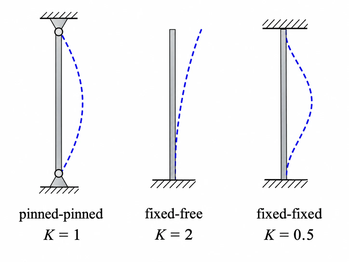
The end restraints govern how much a column is free to curve. Write its effective length as . For ideal arrangements, for pinned-pinned, for fixed-free, for fixed-fixed, and approximately for fixed-pinned. A smaller increases the ideal buckling load because it shortens the effective length. These values assume the restraints act as intended; a joint that can rotate or a frame that can sway may need a different model. Sketch the end conditions before choosing .
Stiffness and the weak axis
Euler buckling depends on flexural rigidity , not just cross-sectional area. For a solid circular section, . For a rectangle, bending about a centroidal axis parallel to the width uses . A section with two possible bending directions generally buckles about the one with the smaller . Convert millimetres to metres before raising a dimension to the fourth power. Increasing column length has an especially strong effect: if doubles with the other inputs unchanged, falls to one quarter.
Limits of the Euler prediction
The formula describes elastic instability of a sufficiently slender, straight column under a centred compressive force. It does not by itself check material yielding, initial crookedness, eccentric loading, imperfections or connection weakness. A short, stocky column may yield before Euler buckling occurs. For a real design, compare the critical load with the applied load and then perform the relevant code-based resistance and safety checks. Never treat the ideal as an automatically allowable working load.
Worked example: Buckling of a pinned steel rod
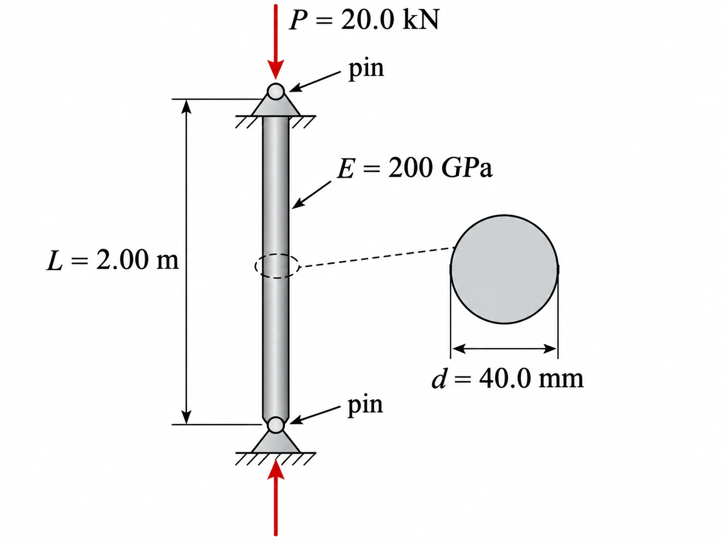
A straight, solid steel rod is long and has diameter . Both ends are ideally pinned, and . A centred compressive force of is applied. Assuming elastic Euler buckling is applicable, find the ideal critical load and the applied-load-to-critical-load ratio.
Show the solution
1. Identify end conditions and convert units. For pinned-pinned ends, . Use , and .
2. Calculate the second moment of area.
3. Apply Euler's formula.
4. Compare loads.
Answer: and . The applied load is below the ideal elastic critical load; this is not a complete safety assessment.
Common mistakes
Selecting an effective-length factor without checking the restraints.
Sketch what can rotate and translate at each end, then select the corresponding ideal .
Using area instead of second moment of area.
Buckling is controlled by bending stiffness , with in .
Forgetting to check the weak buckling axis.
Calculate the second moment of area about each candidate bending axis and use the smaller relevant value.
Treating an ideal Euler load as the safe design resistance.
Also check yielding, imperfections, eccentricity and applicable design requirements.
Check your understanding
1. If a pinned-pinned column length doubles while , and stay constant, what happens to ?
2. What is the ideal effective-length factor for a fixed-free column?
3. What is for a solid circular rod of diameter , about a centroidal bending axis?
Still not sure? Talk it through.
Waypoint Mentor's tutor explains this out loud, works through your own problems on a whiteboard, and checks you've got it. Free to start.