Mohr's circle for plane stress
Engineering · Second-year university engineering · about 10 min
A small piece of material can carry both normal and shear stress, and those components change when you look at a differently angled plane. Mohr's circle collects those changes in one construction. It is particularly useful for finding the largest in-plane stresses and identifying the orientations that matter for design checks.
The key idea
The two in-plane principal stresses are
Here and are normal stresses on perpendicular faces and is the in-plane shear stress. Principal planes have zero shear stress.
Try it yourself
Stress components and signs
Plane stress describes a thin region where the out-of-plane stress components are negligible. Take tensile normal stress as positive. Define positive to act in the positive direction on the face whose outward normal points in the positive direction. The other shear arrows must balance the element's moment. Keep this sign convention throughout: changing it halfway through the calculation changes the predicted orientation. Mohr's circle finds the two in-plane principal stresses. In a full three-dimensional check, the additional principal stress is zero under the plane-stress assumption, so include it when ranking all three principal stresses.
Constructing the stress circle
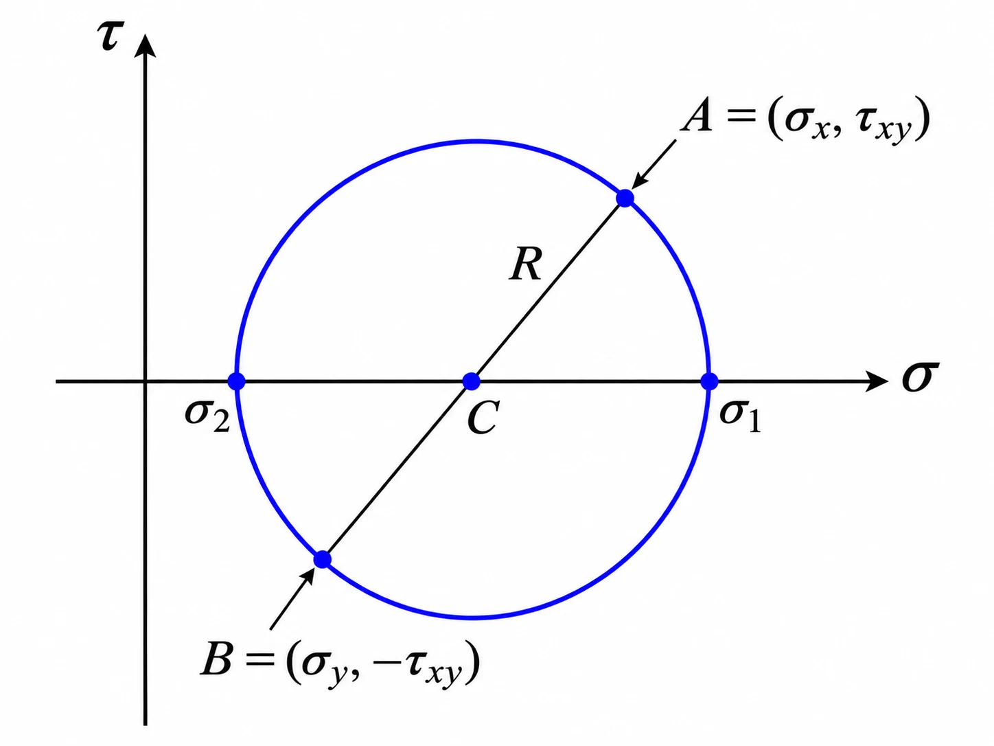
Plot normal stress horizontally and shear stress vertically, with positive upward. Mark and . The midpoint is and the radius is . The circle meets the normal-stress axis at and , which are the principal stresses. The largest magnitude of in-plane shear stress is and occurs where the circle reaches its top or bottom. Do not confuse that with a three-dimensional maximum shear check.
Finding the angle of a plane
An element rotated physically through counterclockwise corresponds to moving around this particular Mohr plot through clockwise from point . To find the major principal direction without an ambiguous tangent quadrant, calculate , then check it gives the larger stress. For a rotated face, use and , where . Angles describe face-normal directions, not lines drawn along the face.
Worked example: Principal stresses in a loaded plate
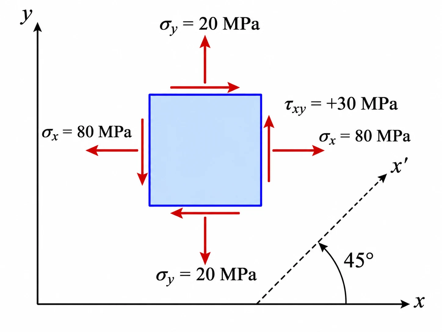
At one point in a thin plate, , and . Find the two in-plane principal stresses, the counterclockwise angle from the direction to the major principal normal, and the maximum in-plane shear stress. Also find and when the axes rotate counterclockwise through .
Show the solution
1. Find the centre and half-difference.
2. Find the radius and principal stresses.
3. Find the principal orientation and maximum in-plane shear.
4. Transform through . Since ,
Answer: . At , .
Common mistakes
Using the full normal-stress difference as the circle offset.
Use , not , in the radius.
Reading the circle angle directly as the physical angle.
The Mohr angle is twice the physical rotation. Halve it and follow the stated shear-axis convention.
Assuming the smaller in-plane principal stress is always the least three-dimensional principal stress.
For plane stress, also consider the out-of-plane principal stress .
Dropping the sign of shear stress.
Record the shear-arrow direction first and retain the sign in transformation equations.
Check your understanding
1. If , and , what is the larger in-plane principal stress?
2. For and , what is the horizontal coordinate of the circle centre?
3. A plane-stress state has and . What is the larger principal stress?
Still not sure? Talk it through.
Waypoint Mentor's tutor explains this out loud, works through your own problems on a whiteboard, and checks you've got it. Free to start.