Part I: Statics · Topic 2 of 8 · 18 min read
Trusses & Structural Analysis
Turn a connected structure into solvable pin-joint equilibrium problems.
What you'll learn
Recognise ideal two-force truss members and determine tension or compression.
Identify simple zero-force members and assess static determinacy.
Apply the method of joints systematically.
Use a method-of-sections cut to isolate desired member forces.
Understand the concepts
What a truss idealisation assumes
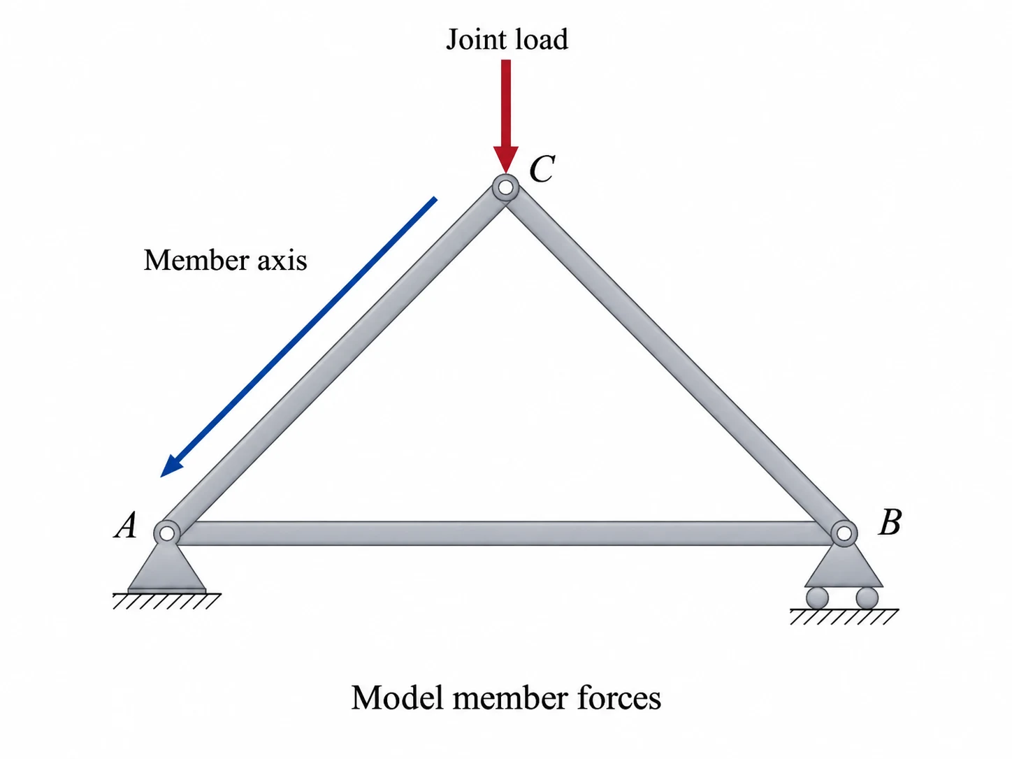
An ideal planar truss consists of straight members connected by frictionless pins with loads applied at joints. Its member force acts only along its own axis: tension pulls away from a joint; compression pushes toward it.
Start with the complete truss
External support reactions usually follow from whole-structure equilibrium. Before solving individual joints, inspect geometry, symmetry and zero-force rules.
Method of joints
At each joint the concurrent member forces obey . Start at a joint with at most two unknown member forces. Assume unknowns pull away from the joint; a negative answer identifies compression.
Try it yourself
Assumptions and sign conventions
Straight, pin-connected members; loads and reactions act at the joints.
Member bending, connection moment and self-weight are neglected unless explicitly included as joint loads.
Use tension-positive member-force sign convention; report tension (T) or compression (C).
Support conditions and geometry must provide a stable structure.
Equations that matter
Step-by-step method
Draw the entire truss, label joints and support reactions.
Solve the external reactions; apply obvious zero-force-member rules where valid.
For joint analysis, choose a joint with no more than two unknown axial forces.
Resolve each member using its actual direction cosines; carry the member signs consistently to adjacent joints.
For sections, cut through the target members and select a side with simple loading.
Verify joint residuals and classify each nonzero force as T or C.
Worked example: Three-member roof brace
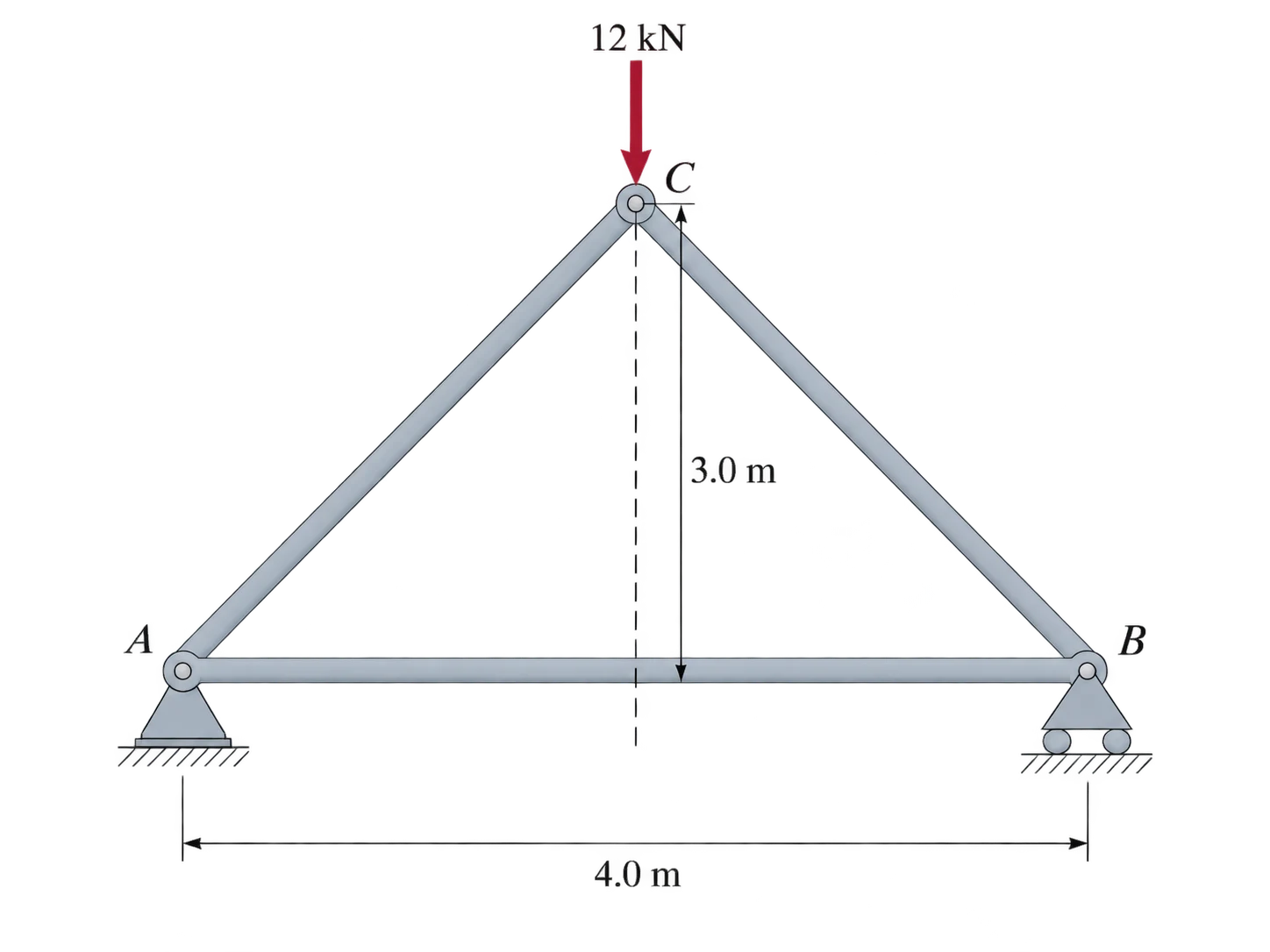
A symmetric triangular truss has supports at and , with apex . A downward force acts at . Determine member forces , , .
Common mistakes
Calling a member tensile simply because its force magnitude is positive.
Forgetting an applied force at a joint when drawing that joint FBD.
Using a zero-force rule without checking all forces at that joint.
Assuming a member-count test alone guarantees structural stability.
Check yourself
When can a two-force member carry a moment?
Why does a negative tension-positive result mean compression?
Which three equilibrium equations are available after cutting a planar truss?
Ready to try it yourself?
Related: Distributed Loads, Shear & Bending
Independent Waypoint Mentor learning material. Not affiliated with or endorsed by any university.