Part I: Statics · Topic 4 of 8 · 21 min read
Distributed Loads, Shear & Bending
Connect the load diagram, internal actions and structural response.
What you'll learn
Find equivalent forces for uniform, triangular and varying loads.
Calculate external reactions before taking sections.
Develop piecewise shear-force and bending-moment equations.
Sketch SFDs and BMDs with correct slopes, jumps and boundary values.
Understand the concepts
External reactions and internal resultants are different
Reactions are external support forces. Shear and bending are internal effects exposed by cutting the beam at location . A single load resultant can solve reactions, but does not replace the distributed load when finding internal-action functions.
State the section-cut convention
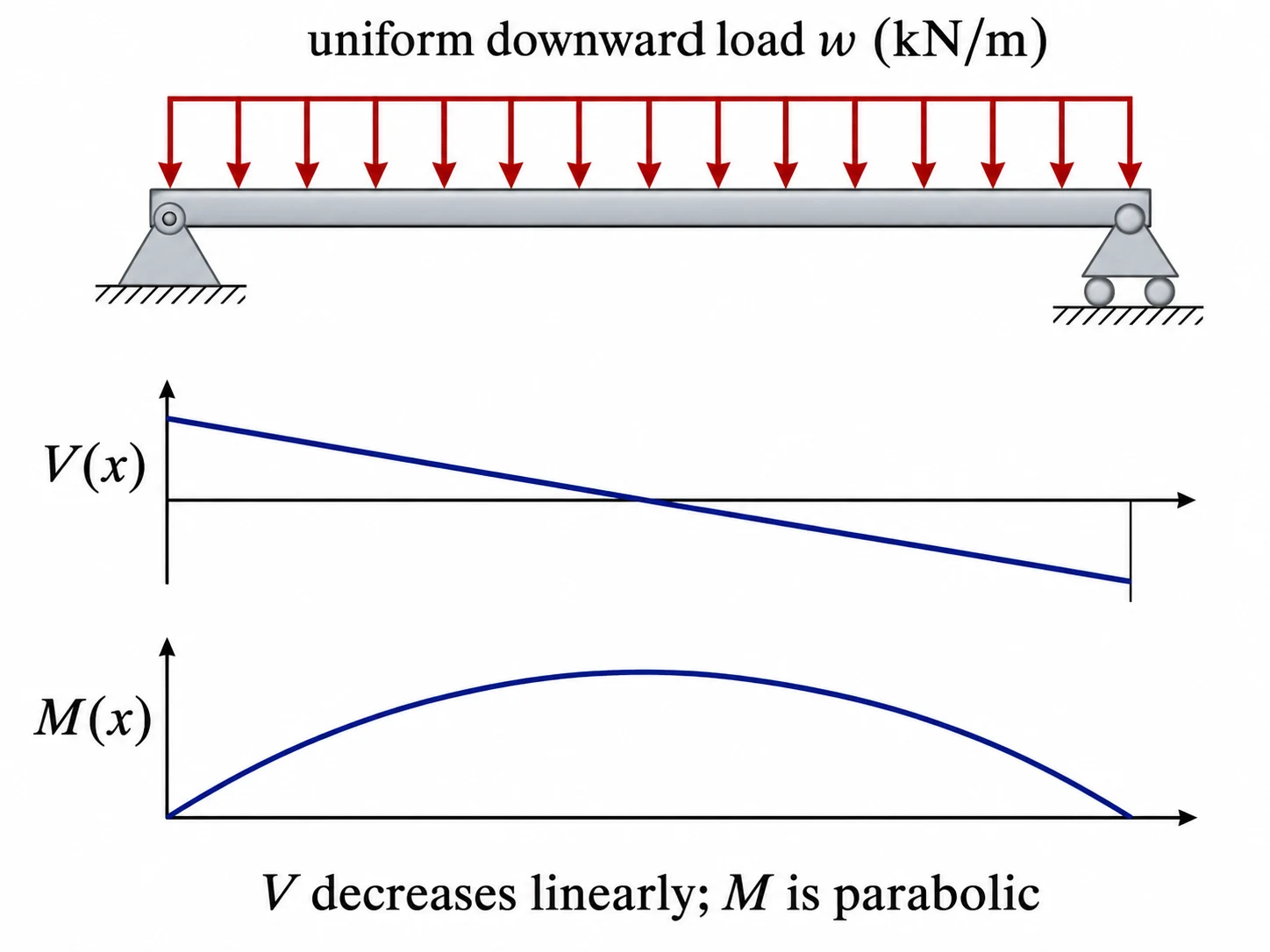
For the LEFT isolated beam segment in these notes, positive acts downward at the cut and positive sagging acts CCW at the cut. This produces and for downward-positive load intensity .
Try it yourself
Assumptions and sign conventions
Straight Euler-Bernoulli-style beam idealisation; static planar loading.
Small deformation is assumed for equilibrium geometry; shear deformation and deflection are outside these introductory examples.
Downward distributed-load intensity is positive in the differential relations shown.
Use N–m or kN–m consistently; do not mix mm with m without conversion.
Equations that matter
Step-by-step method
Draw all support reactions and compute them using whole-beam equilibrium.
Define the x-origin, loading regions and the positive internal sign convention.
Make cuts in every interval separated by point loads, couples or loading changes.
Apply section equilibrium (or integrate load and shear) to obtain and .
Apply point-force jumps to V and couple jumps to M where needed.
Check support-end boundary conditions, moments at cuts and the location of maximum .
Worked example: Uniformly loaded simply supported beam
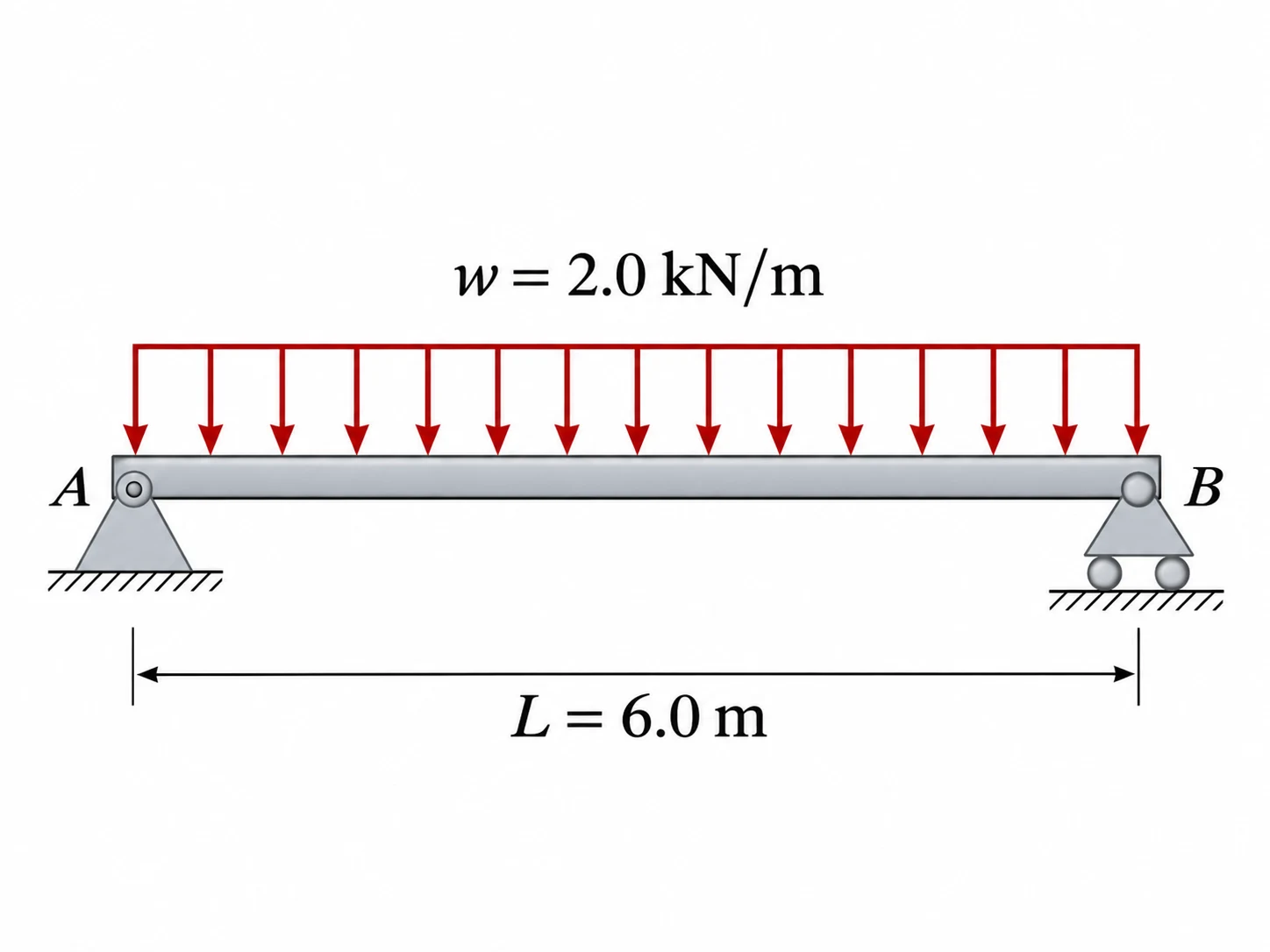
A simply supported beam carries a uniform downward load along its full span. Find reactions, , and maximum positive bending moment.
Common mistakes
Using the load resultant at midspan to compute every internal shear instead of retaining the actual load over each section.
Misplacing a triangular load centroid.
Drawing a straight moment line under uniform loading (it must be parabolic).
Confusing the location of zero shear with a zero bending moment.
Check yourself
What does a downward point load do to a shear-force diagram?
Where is the centroid of a triangular load?
Why can a bending moment be nonzero when the shear force is zero?
Ready to try it yourself?
Related: Force Systems & Equilibrium · Trusses & Structural Analysis · Mass Moments & Rigid-Body Dynamics
Independent Waypoint Mentor learning material. Not affiliated with or endorsed by any university.