Part II: Flow and Conservation · Topic 4 of 8 · 26 min read
Bernoulli and Mechanical Energy
Connect pressure, speed, elevation, pumps, turbines and losses.
What you'll learn
Explain pressure, velocity and elevation head as energy per unit weight.
Check the assumptions behind ideal Bernoulli analysis.
Apply the extended energy equation across components.
Distinguish hydraulic power from shaft power using efficiency.
Understand the concepts
Mechanical-energy picture
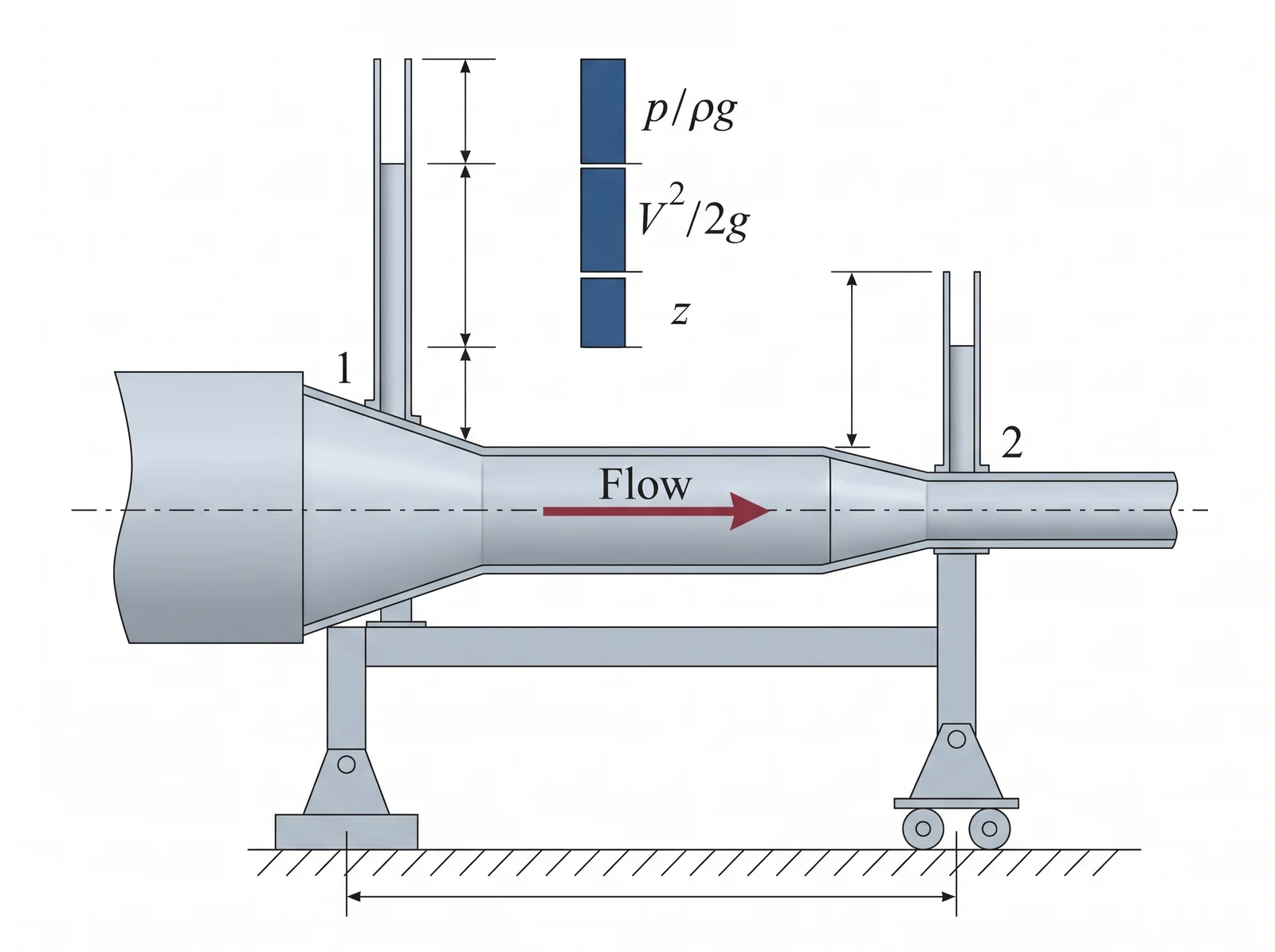
Pressure head, velocity head and elevation head are three ways fluid mechanical energy is carried. Each head has units of length even though the physical meanings differ. Pressure can turn into speed without creating net energy.
Bernoulli is conditional
The familiar Bernoulli relation applies along a streamline in steady, inviscid, incompressible flow without shaft work. It should not be applied across a pump, significant friction or a boundary layer without accounting for additional effects. Distinguish ideal streamline results from section-averaged engineering models.
Irreversible losses
Real devices dissipate mechanical energy through wall friction, separation, fittings and mixing. Represent that dissipated mechanical energy by a positive head loss in the flow direction. A loss coefficient must be based on the velocity specified for that component.
Pumps and turbines
A pump adds mechanical head to the fluid, while a turbine extracts it. Efficiency converts between hydraulic power and external shaft power; for a pump, shaft input exceeds hydraulic output. For a turbine, shaft output is smaller than hydraulic input.
Free-surface simplifications
At a broad, exposed reservoir surface, gauge pressure is zero and the velocity may be negligible compared with a pipe jet. These simplifications must be justified using the relative areas and flow conditions. Elevation differences must use a consistent datum.
Solving without a sign mistake
Write the full extended energy equation between labelled stations before cancelling equal terms. Place pump head on the input side, turbine extraction and losses on the output side. Check the final head and power are positive for the stated operation.
Assumptions and sign conventions
One-dimensional section mean speeds with kinetic energy correction factor taken as unity.
Steady incompressible flow unless noted.
No significant heat/thermal energy bookkeeping for the mechanical-energy model.
Head loss is nonnegative in the defined flow direction.
Equations that matter
Step-by-step method
Label stations, flow direction, free surfaces, and a single elevation datum.
State whether the ideal or extended equation is justified.
Calculate section velocities from continuity and identify every loss reference speed.
Solve the head balance symbolically before numerical substitution.
Compute power and efficiency only after finding the hydraulic head; check energy direction.
Worked example: Pressure recovery in a short diffuser
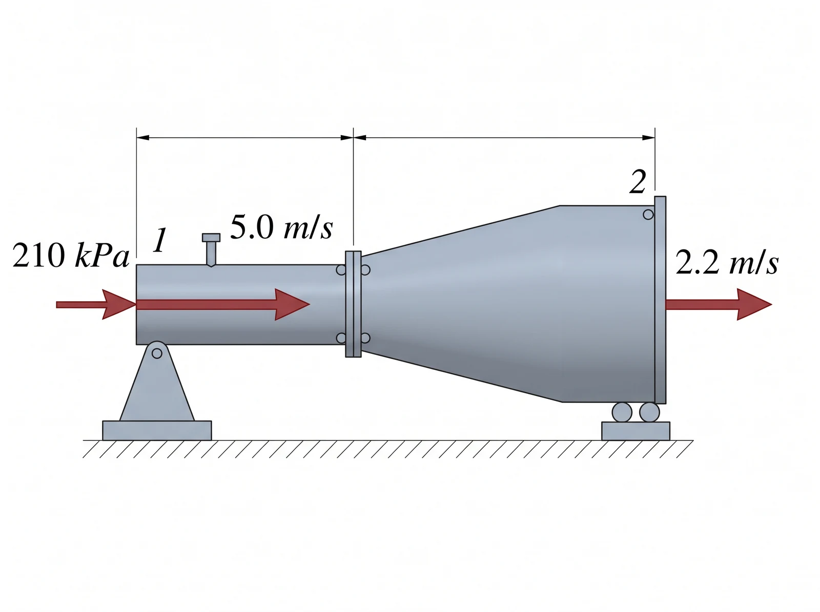
A steady, horizontal water stream expands from a section where to one where . If gauge and losses are negligible, find for .
Common mistakes
Using Bernoulli across a pump without its head term.
Using a fitting loss coefficient with the wrong reference speed.
Adding efficiency to hydraulic power instead of dividing for a pump.
Cancelling unequal velocities at different-sized sections.
Check yourself
Why does pressure often rise as a diffuser slows the flow?
Where does pump head enter the extended equation?
Why is shaft input larger than hydraulic output for a pump?
Ready to try it yourself?
Related: Internal Flow and Pipe Losses
Independent Waypoint Mentor learning material. Not affiliated with or endorsed by any university.