Part I: Physical Foundations · Topic 3 of 8 · 24 min read
Flow Kinematics and Continuity
Describe local velocity fields and the conservation of mass.
What you'll learn
Distinguish pathlines, streamlines and velocity vectors.
Calculate local speed, direction and material acceleration.
Apply continuity across junctions and changing flow areas.
Use storage balances to follow changing tank levels.
Understand the concepts
Eulerian and particle viewpoints
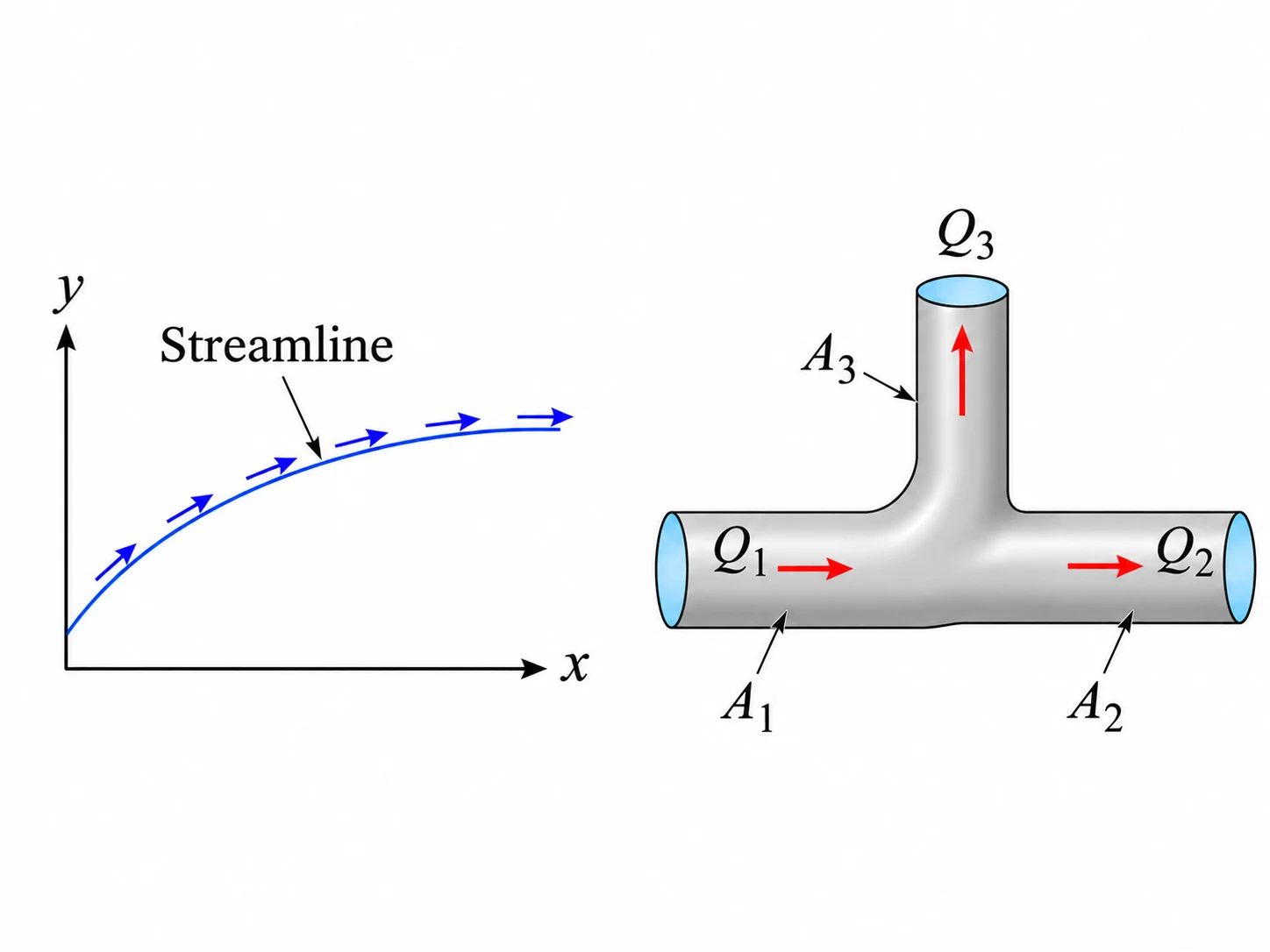
A velocity field specifies the velocity at each location rather than tracking one labelled particle. A streamline is tangent to instantaneous velocity everywhere, whereas a pathline follows a material particle in time. These coincide for a steady velocity field.
Vector speed versus components
A two-dimensional velocity has horizontal and vertical components that may have different signs. Speed is the magnitude of the velocity vector and cannot be negative. Use an angle convention and a quadrant-aware inverse tangent when reporting direction.
Material acceleration
A moving particle may accelerate in steady flow if it passes through locations with different velocity. Material acceleration contains a local time-rate term and a convective term. A simple gradient is therefore not automatically the particle acceleration.
Mass conservation
A control volume cannot create or destroy mass. Under steady flow with uniform section velocities, sum of inlet mass flow rates equals sum of outlet mass flow rates. Density cancels only when it is effectively the same at each section.
Area, discharge and mean speed
The volume flow rate is the integral of normal velocity over an outlet area. For a uniform or suitably averaged profile, is exact. When a pipe narrows at fixed incompressible flow rate, mean speed rises.
Assumptions and sign conventions
Velocity fields are measured relative to a fixed Cartesian frame unless stated otherwise.
Use cross-sectional mean speeds in one-dimensional continuity relations.
Treat the liquid as incompressible only where explicitly specified.
For tank storage, the area is constant over the modelled level interval.
Equations that matter
Step-by-step method
Identify the control volume or spatial point and draw all flow arrows.
Compute section areas or evaluate field components with consistent units.
Write vector definitions or a signed mass balance before substituting numbers.
Solve for the requested speed, discharge, direction or storage change.
Check mass balance and whether the speed and level trend make physical sense.
Worked example: Speed increase through a smooth reducer
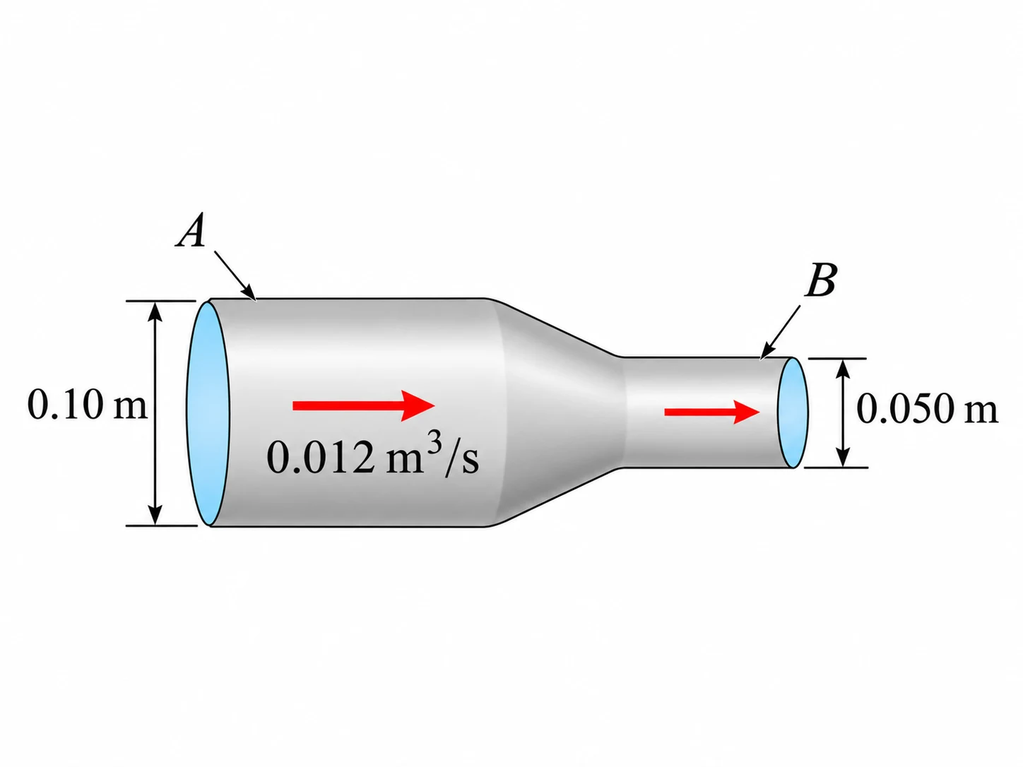
Water passes steadily through a horizontal reducer. The upstream and downstream diameters are and , and the discharge is . Estimate the mean speed at each section.
Common mistakes
Calling a velocity component the overall speed.
Forgetting the convective terms in steady-flow acceleration.
Assuming equal speed when a pipe diameter changes.
Reversing inlet/outlet signs in a storage balance.
Check yourself
Can steady flow have nonzero material acceleration?
How does pipe speed change when diameter is halved at constant discharge?
What does a rising tank level say about total inflow relative to outflow?
Ready to try it yourself?
Related: Control-Volume Momentum
Independent Waypoint Mentor learning material. Not affiliated with or endorsed by any university.